As an Amazon Associate & Influencer, we earn from qualifying purchases you might make if you click any of the links or buttons on this page at no expense to you.
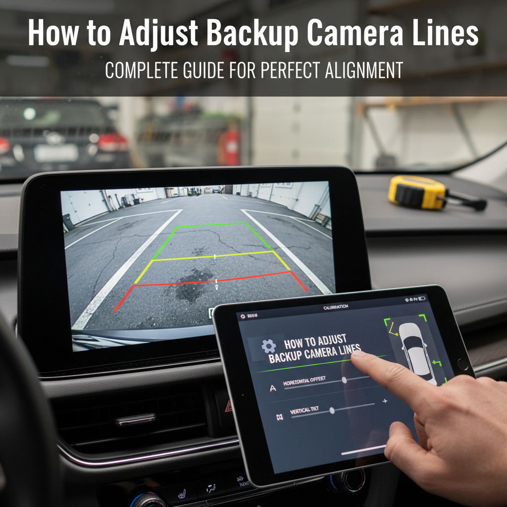
To adjust backup camera lines, first confirm that your camera or screen actually supports moving them. On an adjustable system, secure the camera, place the reference marks specified in its manual, then move the guide points to match those marks while the vehicle stays stationary. Save the setting and check it again in the normal reversing view.
A menu that says Guidelines On/Off only changes visibility. It does not necessarily let you change width or distance. Steering-responsive lines are a separate case: a wrong predicted path needs the vehicle’s diagnostic procedure, not a fixed grid dragged until it looks straight.
Set up with the vehicle secured on level ground. Apply the parking brake and switch the vehicle off before placing or moving markers behind it. Return to the driver’s seat before activating the camera; keep everyone out of the reversing path. Guidelines supplement direct checks and mirrors—they do not certify clearance.
Jump to: Can your lines be adjusted? · Adjustment steps · Real menu examples · Factory and moving lines · Troubleshooting · Useful tools · Final checks · FAQs
Can you adjust your backup camera’s parking lines?
Identify the vehicle’s year and camera equipment, or the exact aftermarket camera and head-unit models. Include a camera-retention interface if an original camera feeds a replacement radio. The important question is which component draws the lines. Buying a different camera will not add a missing adjustment menu to the existing screen.
| What you have | What you can change | Best next step |
|---|---|---|
| An editable guide with corner handles, arrows or width controls | The overlay position/shape within the supported range. | Use the documented reference layout and adjustment procedure below. |
| A factory menu with fixed/dynamic line switches | The displayed line types; geometric adjustment is not established by an on/off switch. | Check the exact owner’s manual before looking for a calibration menu. |
| Lines built into an aftermarket camera’s video | Often visibility through a documented camera control; movable geometry is not guaranteed. | Check the camera manual as well as the receiver manual. |
| Steering-responsive or surround-view guides that are wrong | The relevant system may require diagnosis, initialization or service calibration. | Follow the vehicle-specific procedure, especially after camera/body/steering work. |
What the colored lines actually tell you
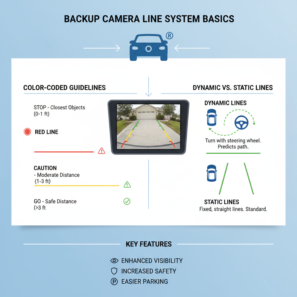
Red, yellow and green usually distinguish nearer and farther parts of the display. They are not universal measurements or traffic-light permission to reverse. Look up the distance labels for your system. Do not assign 1, 3, 6 or 10 feet to a colored band from an unrelated guide.
Check what the side lines represent, too: vehicle width, a width with a stated allowance, an approximate path or another reference. A centerline intended for a trailer hitch is not automatically the vehicle’s clearance boundary. Mirrors, a tow ball, a bike rack and an overhanging load still need separate clearance checks.
How to adjust backup camera lines on a supported system
1. Fix the camera view before moving the overlay
Start with a clean, upright picture and a secure mount. Close the tailgate or hatch fully if it carries the camera. Look for a shifted bracket, damage or recent work that changed its position. Set the camera’s permitted mounting direction and aiming first; moving it afterward invalidates the alignment you just made.
If the horizon is tilted, correct a permitted mounting problem rather than bending the grid to disguise it. If the picture is upside down or left/right is wrong, resolve the camera orientation problem first. Do not rotate a fixed factory insert or twist a sealed lens assembly as an improvised adjustment.
A dirty lens makes reference marks hard to see; cleaning does not reposition a correctly generated overlay. Use the backup-camera cleaning guide if road film or droplets obscure the view.
2. Choose the reference layout for this exact camera and screen
Open the installation/operation manual at Parking Guide Adjustment, Guidelines Setup or the equivalent. Check the drawing’s reference point: a dimension measured from the rear bumper is different from one measured from the camera lens. Use the stated width allowance and distances, including their units.
For a procedure that calls for ground markings, measure them on a clean, flat surface with the vehicle secured and off. Use straight, visible markers that suit the surface. If the camera cannot see the prescribed layout, resolve its mounting/view limitations before dragging the handles to their limits.
- Keep one measurement convention. Record each distance and unit before laying it out. Do not mix feet with meters or round a metric diagram to a convenient number of feet.
- Choose one tape edge as the reference. A wide strip has two edges. Mark and align the same edge at every point rather than measuring to one edge and adjusting to the other.
- Do not assume the parking-space width equals the vehicle width. A stall boundary is useful only when the documented method uses it and the vehicle is positioned as directed.
- Keep markers stationary. Loose or peeling tape is a poor reference. Re-secure the vehicle and switch it off before stepping behind it to correct a marker.
Garmin’s BC 50 alignment procedure is a useful example of a different method: it uses a visible curb, driveway edge or parking line, with the vehicle deliberately positioned alongside the reference, then repeats the check on the other side if necessary. That does not mean simply stretching the grid to fill any parking bay.
LAYOUT DETAIL
Measure to one clearly defined edge
REAR BUMPER
↕
Specified offset
Use the distance and measuring point in your exact manual.
CHOSEN REFERENCE EDGE ↑
01 Measure to this edge.
02 Match the guide to the same edge.
Using the opposite edge changes the reference by the tape’s width.
Schematic, not to scale. The rear bumper is the datum only when your manual specifies it; this is not a universal target layout.
3. Open the real adjustment control
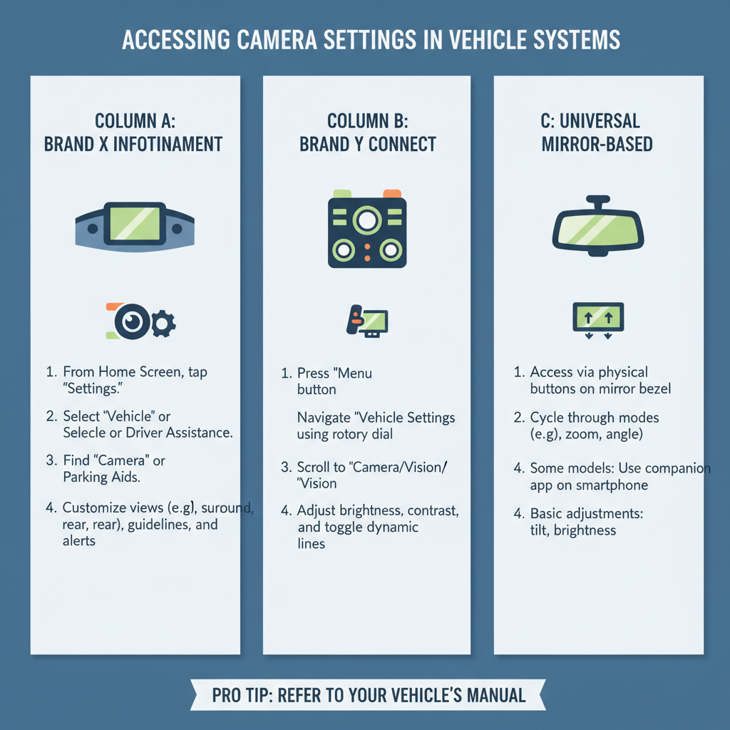
Use the documented camera/settings mode while parked. A receiver may require the parking brake to be applied before adjustments are available. Do not bypass that input. Select the rear camera/channel you intend to adjust, and take a photo of the original settings before changing them.
| Documented example | Adjustment control | Important limit |
|---|---|---|
| Sony XAV-AX8100/XAV-AX8150 | General → Rear View Camera → Guide Line Adjust. Select the near or far section, then use position/width controls. | This changes the displayed guide. Normal/Reverse is a separate image-mode choice. |
| Pioneer DMH-ZF8550BT (regional model example) | System → Camera settings → Parking Assist Guide Adjust; drag or use the on-screen controls. | The manual requires its marking layout and parking brake; availability can depend on the connected camera/iDatalink configuration. |
| Garmin BC 50 with a compatible navigation device | From camera view, use the guideline control or menu → Adjust Video, as supported by the device. | Adjust the selected camera to the documented references, then confirm with the check control. |
4. Match the near and far points without distorting the guide
Where the system provides separate handles, select one point or section and make small changes. Align it with the prescribed reference, then check the opposite side and the farther points. Revisit the near points after changing width or angle, because one control may move more than one part of the grid.
Perspective makes ground lines converge in the picture. Do not force the overlay into a rectangle simply because the real reference layout is rectangular. Judge its match to the visible measured marks, using the manual’s intended shape and symmetry requirements.
A good near match with a poor far match is a reason to recheck the reference layout, selected view, permitted camera position and the correct adjustment point. If one side runs out of adjustment, stop. Stretching the other side until the grid looks tidy can hide an installation problem without making the reference useful.
5. Set distance bars only where that function exists
Some controls let you move or resize the guide as a whole; others expose individual points. Do not assume every red, yellow or green crossbar has an independent distance setting. Follow the supported adjustment and measure from the datum shown in the drawing.
Keep the camera in the documented normal reversing view. A zoomed, wide-angle or top-down mode can present a different picture and different guide behavior. Do not adjust in one view and assume the result applies to all views. A line on the road also cannot establish clearance to a raised bumper, post or overhanging obstacle.
6. Save, leave the menu and verify the normal view
Use the model’s confirm/back/save action. Re-enter the usual camera view, then check again after a normal restart. If the settings revert, diagnose retention or configuration rather than repeating the alignment each time. A global factory reset is unnecessary when the problem is one adjustable guide.
Keep the measurement record and a parked photo of the finished view. They give you a useful baseline after later camera, tailgate or radio work. Recheck after a documented mounting change; there is no universal monthly, annual or seasonal recalibration interval for every reversing camera.
Factory and dynamic guidelines: when dragging lines is the wrong fix
An on/off menu is not missing a step just because it offers no drag handles. For example, the 2023 UK Honda Jazz e:HEV manual describes fixed-guideline visibility and a dynamic-guideline switch for steering-responsive movement. Those user controls do not establish a manual width or distance adjustment for another Honda, or even another camera package.
A moving line that disappears in a particular mode is not automatically faulty. Ford’s documented guideline behavior includes active lines that fade with steering position and do not display when the wheel is straight on the covered system. The same page notes that active guides may need a short drive to reset after power loss. Use the matching vehicle instructions; do not copy a speed, steering-lock sequence or battery reset from a different model.
If the predicted path remains wrong, the camera has moved after damage, or the fault followed camera/steering/body work, have the installation and applicable service requirements checked. The useful diagnosis covers the correct camera/interface, mounting, software/configuration and relevant faults, with initialization or calibration only where the service procedure requires it. Buying a generic scan tool does not establish that it supports the needed function.
Troubleshooting crooked, doubled or missing camera lines
| Symptom | Check first | What to do |
|---|---|---|
| Two different grids appear | Camera-generated lines plus receiver-generated lines. | Switch one documented overlay off and observe which remains; keep the appropriate single guide. |
| No adjustment option, only On/Off | The feature list for the exact screen/camera combination. | Use the visibility control if wanted; do not hunt for an undocumented engineering menu. |
| The picture and guides both seem tilted | Tailgate position, camera mount, image orientation and level test ground. | Correct the supported viewing/mounting issue before changing guide geometry. |
| Near points align, distant points do not | Reference positions, selected view and the near/far handles. | Recheck the measured layout and supported camera position; do not hide the discrepancy with one width control. |
| Lines are missing after a battery event | Enabled line type, supported view and the vehicle’s initialization instructions. | Use the exact procedure; a missing line alone does not prove camera failure. |
| Guides move the wrong way or remain offset | The intended rear-view orientation and dynamic-system configuration. | Restore the correct view first; persistent predicted-path errors need the vehicle-specific diagnosis. |
| Lines vanish in zoom or trailer view | The manual’s behavior for that camera mode and trailer connection. | Return to the supported reversing view before treating it as a fault. |
| A previously correct grid no longer matches | Recent mount, camera, tailgate, radio or vehicle-height changes. | Find what changed; use the applicable installation/service requirements before realigning. |
| Correct adjustment disappears after restart | Whether the setting was confirmed and retained. | Check model-specific settings/software and installation power retention; avoid repeated global resets. |
How to remove double parking lines
OVERLAY DIAGNOSIS
Two sources can draw two sets of lines
A · CAMERA / INTERFACE
A
Lines already in the video.
B · RECEIVER
B
An overlay added by the screen.
A + B · DISPLAY
A
B
Both layers appear together.
Turn off the receiver’s documented guides. → If lines remain, check the camera/interface layer.
Schematic overlays, not product screenshots or distance scales. Make the check while stationary; use the exact controls rather than cutting an unidentified wire.
A camera may use a menu, button, switch or documented wire loop to disable its own lines. There is no universal wire color to cut. Verify the exact harness revision and follow its power-off, insulation and sealing instructions. Do not alter an unknown loop, supply or ground wire to move the grid.
For a RAM with missing lines or a frozen camera screen, the RAM backup-camera troubleshooting guide separates radio restarts from camera and tailgate checks. Use it for that vehicle-specific problem rather than treating every missing guide as a manual alignment issue.
Useful tools for a measured guideline setup
Use a sound tape measure and suitable removable markers you already own. The two options below make sense for a supported manual layout, but neither unlocks a factory adjustment menu or performs electronic calibration. The camera/receiver manual and a compatible surface matter more than the brand on the tool.
| Tool / role | Why choose it | Check before buying | Current price |
|---|---|---|---|
| STANLEY PowerLock 33-425 25-foot tape measure | A straightforward way to measure the specified offsets and distances. | This is the feet/inches model; use a suitable metric measure if your layout is metric. | Check Current Price on Amazon |
| ScotchBlue Original 2090-48NC 1.88-inch × 60-yard roll | Visible temporary reference edges on a suitable clean, dry surface. | Check surface suitability and adhesion first; do not assume it will stick to rough, dusty or wet pavement. | Check Current Price on Amazon |
STANLEY PowerLock 33-425: a practical measuring tool
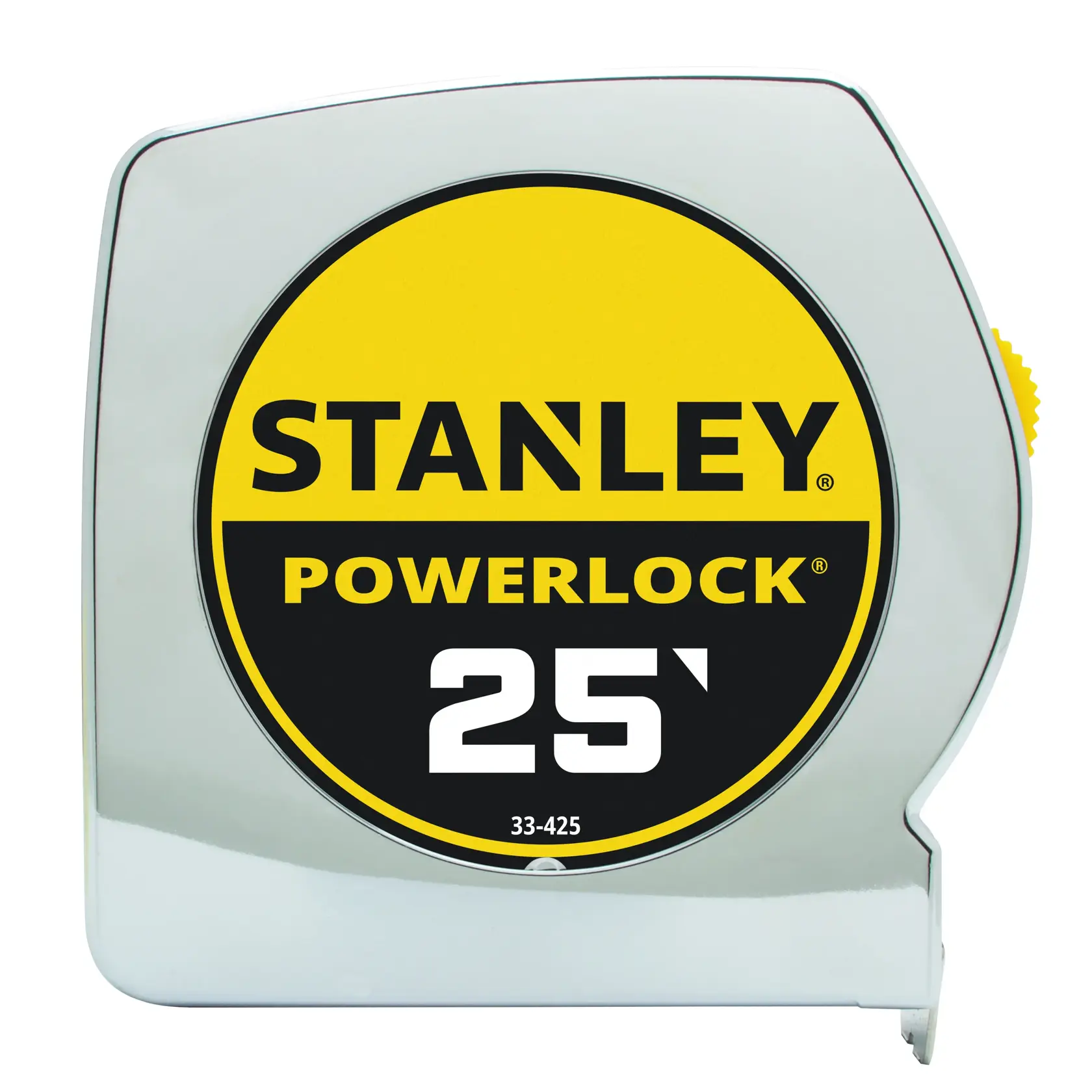
Choose it if: the procedure gives feet/inches dimensions and you need a conventional tape for ground-reference measurements.
Skip it if: you already have a sound measure, need metric graduations, or are dealing with a service calibration rather than a ground layout.
The 33-425 is a sensible choice for this job: a 25-foot blade, manual lock and sliding Tru-Zero end hook cover ordinary layout measurements without adding an electronic tool to a simple task. Its chrome-colored case is ABS, and the blade has a Mylar coating. Choose it for the physical measuring job, not as a camera-specific accessory.
Read the correct graduations and keep the blade straight along the measured line. A damaged hook, kinked blade or diagonal measurement can undermine the reference before you touch the screen. This model’s imperial scale is also a poor match if you would have to repeatedly convert a metric calibration drawing; use a metric tape instead.
My recommendation: buy it if you need a useful general-purpose feet/inches tape. Keep the one you have if it is undamaged and readable. Removable markers and the exact layout instructions are still separate requirements.
ScotchBlue Original 2090-48NC: temporary marks on a suitable surface

Choose it if: the camera procedure calls for visible ground markings and the surface is compatible with this removable painter’s tape.
Skip it if: the ground is rough, wet, dusty or unsuitable for the adhesive, or the manual requires a different marker or target.
This is the single 1.88-inch-wide, 60-yard roll. Its blue backing gives you a visible edge to match on the camera screen. I favor a removable marker over a permanent driveway mark, but only where the tape adheres securely and the surface can tolerate it. Test a small area first and remove the marks when the setup is finished.
3M describes Original 2090 for smooth or lightly textured surfaces such as tile, glass and trim; that is not a blanket approval for every garage coating or driveway. Do not buy it expecting reliable adhesion to dirty asphalt or rough concrete. A lifting strip changes the reference. Choose a suitable location or the marker specified by the camera manufacturer instead.
My recommendation: use it for clear temporary edges where the surface check passes. Measure to one chosen edge of the strip consistently. The roll does not include a measuring tool, camera targets or a factory calibration procedure.
Verify the result before relying on the guides
Start with a stationary comparison to the measured references. You do not need to reverse toward a wall or a person to find out whether the overlay matches them. Switch the vehicle off and secure it before getting out to measure or move anything.
Keep slope effects separate from alignment. Toyota’s rear-view monitor guidance explains that its ground-distance references assume a flat surface and can disagree with the real scene on slopes. Do not recalibrate a correct flat-ground guide to make a steep driveway look right. A changed load or ride height also calls for the applicable system instructions, rather than a guessed seasonal adjustment.
Frequently asked questions
Can I adjust backup camera lines without a calibration tool?
Yes, if your system provides user-adjustable guides and a reference-layout procedure. A measuring tool and suitable markers may be all that layout needs. That is different from an OEM service calibration, which can require specified targets, equipment and software.
Why are my backup camera lines not aligned with the parking space?
First check that the vehicle is positioned correctly, the ground is level, the intended view is selected and the mount has not moved. Parking-space edges are not automatically vehicle-width references. Use them only as directed by your system’s documented method.
How far behind the bumper is the red line?
There is no universal distance. Check the exact owner’s or camera manual and its stated measuring point. A red band may mark a near zone or another reference; it does not prove that every part of the vehicle has that much clearance.
Why won’t my parking lines move when I turn the steering wheel?
They may be static guides, the dynamic option may be disabled, or the selected view may not support moving lines. Confirm the feature first. If a previously working steering-responsive guide has stopped, use the vehicle-specific initialization or diagnostic instructions.
Can I turn off backup camera guidelines?
Only where the system supports it. Check both receiver and camera controls, particularly if two grids appear. Turning off one overlay does not necessarily remove lines generated elsewhere. Use the exact instructions before changing a switch or wire loop.
Should I disconnect the battery to realign the lines?
No—battery disconnection is not a general alignment method. It cannot correct a shifted mount or supply a missing adjustment feature, and some systems need initialization after power loss. Use the supported settings or service procedure for the symptom.
Do I need a new camera if the guides are crooked?
Not until the cause is identified. Check the mount, image orientation, selected view, overlay source and any supported adjustment first. Replace a camera only for a confirmed fault or an incompatible installation, with the correct power, signal, connector and integration requirements.
Make the reference accurate before making it look neat
Confirm the adjustment exists, put the camera in its correct final position, and follow the exact reference layout. Match the supported guide points, save and verify. If a factory predicted path is still wrong, get the proper diagnosis before buying a camera or trying to hide the error with another grid.