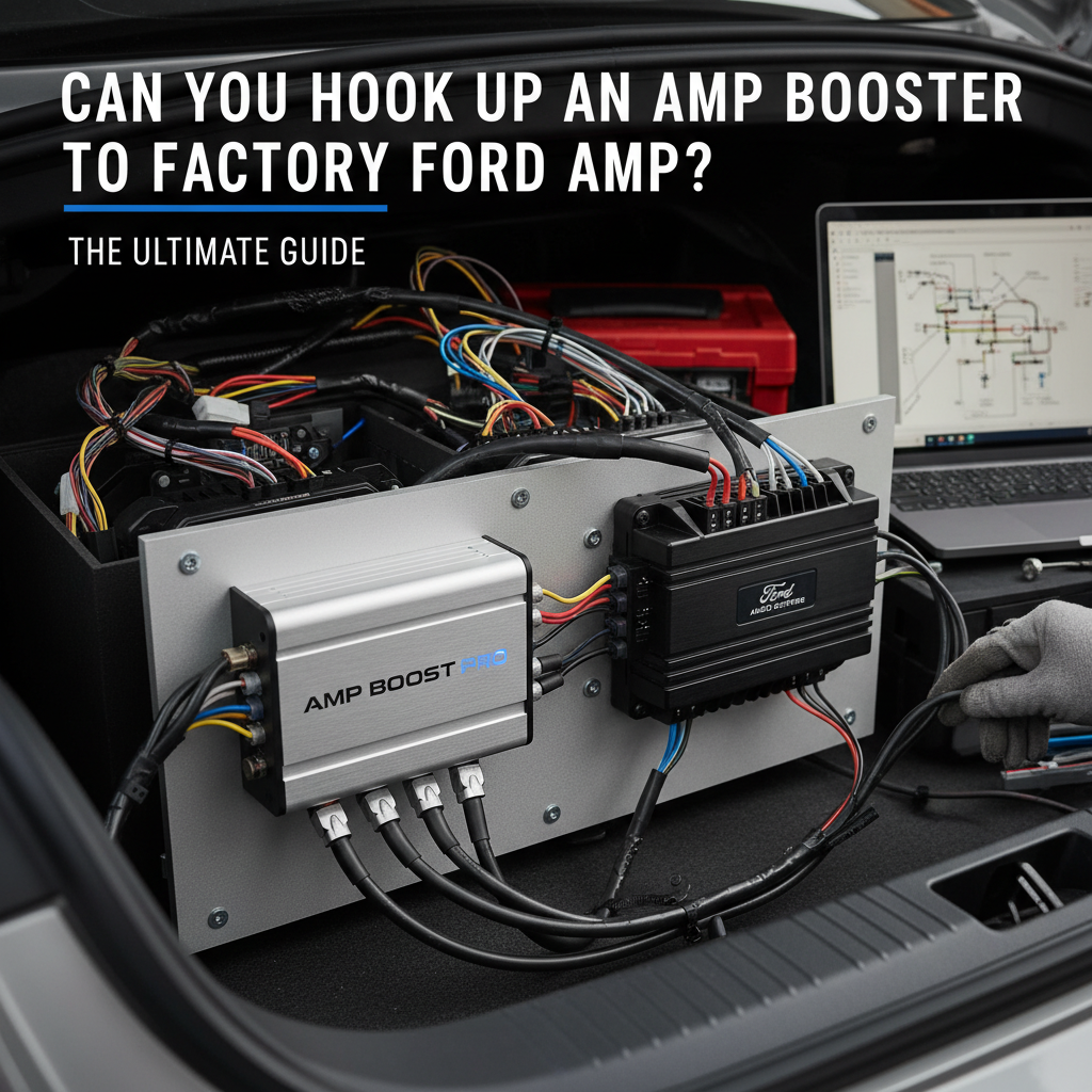
Yes, you can connect an amp booster to a factory Ford amplifier using line output converters (LOCs) or by tapping into pre-amp signals, but success depends on your specific Ford audio system configuration and the booster’s input requirements. Most factory Ford systems require signal conversion or bypass methods to integrate aftermarket amplification effectively.
Ford’s factory audio systems present unique challenges for aftermarket amplification upgrades. Understanding your vehicle’s specific audio architecture determines the most effective integration approach. Our engineering analysis reveals that proper installation requires careful consideration of impedance matching, signal levels, and power distribution.
Contents
- Understanding Ford’s Factory Amplifier Systems
- Signal Extraction Methods for Amp Boosters
- Amp Booster Compatibility Assessment
- Installation Procedures and Best Practices
- Common Integration Challenges and Solutions
- Performance Optimization Strategies
- Technical Specifications Comparison
- Troubleshooting Common Issues
- Professional Installation Considerations
- Cost-Benefit Analysis Framework
- Frequently Asked Questions
- Advanced Integration Techniques
Understanding Ford’s Factory Amplifier Systems
Ford implements several distinct audio system configurations across their vehicle lineup. Each system requires different integration strategies for successful amp booster installation.
Premium Audio System Identification
Ford’s premium audio systems typically feature factory amplifiers mounted in specific locations. The Sony premium system appears in F-150 models from 2015-2020, while Bang & Olufsen systems equip higher-trim vehicles. These systems process audio signals differently than base configurations.
Premium systems often incorporate digital signal processing (DSP) that can complicate aftermarket integration. The factory amplifier receives pre-processed signals from the head unit, making direct connection challenging without proper adapters.
Base Audio System Characteristics
Base Ford audio systems route signals directly from the head unit to speakers without intermediate amplification. These configurations offer simpler integration paths for amp boosters. Speaker-level signals provide the most accessible connection points for aftermarket amplification.
Base systems typically operate at 4-ohm impedance with power output ranging from 15-25 watts RMS per channel. Understanding these specifications helps determine appropriate booster selection and wiring requirements.
Signal Extraction Methods for Amp Boosters
Successful amp booster integration requires extracting clean audio signals from Ford’s factory system. Multiple extraction methods accommodate different system configurations and installation preferences.
Line Output Converter Integration
Line output converters (LOCs) transform speaker-level signals into low-level RCA outputs suitable for aftermarket amplifiers. High-quality LOCs maintain signal integrity while providing proper impedance matching.
Install LOCs at speaker wire locations behind the head unit or at individual speaker connections. This method works effectively with both premium and base Ford audio systems. Choose LOCs with adjustable gain controls to optimize signal levels for your specific amp booster.
Premium LOCs incorporate signal sensing capabilities that automatically trigger amplifier turn-on when audio signals are detected. This feature eliminates the need for separate remote turn-on wire installation in many Ford applications.
Pre-Amp Signal Tapping
Advanced installers can access pre-amp signals directly from Ford’s head unit harness. This method provides cleaner signals compared to speaker-level conversion but requires detailed wiring knowledge.
Pre-amp signal locations vary significantly between Ford model years and trim levels. Consult vehicle-specific wiring diagrams before attempting direct signal extraction. Improper connections can damage sensitive head unit circuits.
Use high-impedance test equipment to verify signal presence and levels before making permanent connections. Pre-amp signals typically range from 0.5-2.0 volts RMS, matching most aftermarket amplifier input requirements.
Amp Booster Compatibility Assessment
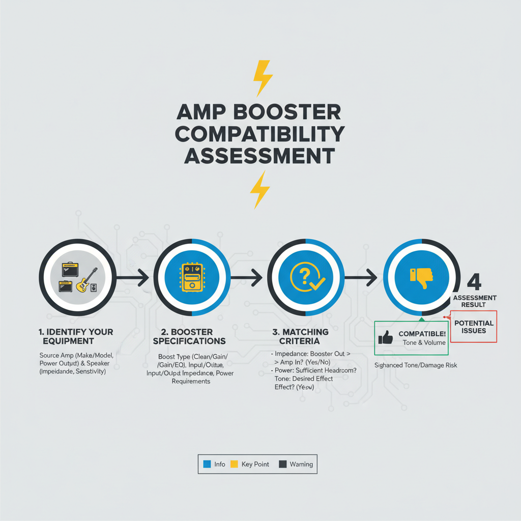
Not all amp boosters integrate successfully with Ford’s factory systems. Compatibility depends on input sensitivity, impedance characteristics, and power requirements.
Input Sensitivity Matching
Ford’s factory audio systems produce varying signal levels depending on configuration and volume settings. Amp boosters with adjustable input sensitivity accommodate these variations most effectively.
Measure your Ford’s maximum clean signal output using an oscilloscope or quality multimeter. Match this measurement to your chosen amp booster’s input sensitivity range for optimal performance. Mismatched sensitivity causes distortion or insufficient output levels.
High-sensitivity boosters (0.2-0.5V input) work well with factory head unit pre-amp outputs. Lower sensitivity units (1-4V input) require speaker-level signals or LOC conversion for proper operation.
Power Supply Considerations
Amp boosters draw additional current from your Ford’s electrical system. Calculate total current draw to ensure adequate alternator capacity and prevent voltage drops during high-output operation.
Most compact amp boosters consume 10-30 amperes at full output. Add this draw to your vehicle’s existing electrical load to determine if alternator upgrades are necessary. Ford’s standard alternators typically provide 130-220 amperes depending on engine size and model year.
Install appropriate fusing at the battery connection point using ANL or MEGA fuses rated 25% above the amplifier’s maximum current draw. This protection prevents electrical fires in case of short circuits or component failures.
Installation Procedures and Best Practices
Proper installation ensures reliable operation and prevents damage to both factory and aftermarket components. Follow systematic procedures for professional-quality results.
Wiring Harness Preparation
1. Disconnect the vehicle’s negative battery terminal before beginning any electrical work
2. Remove necessary interior panels to access head unit and speaker wire locations
3. Identify appropriate signal extraction points using vehicle-specific wiring diagrams
4. Test all connections with appropriate meters before making permanent splices
Use high-quality crimp connectors or solder joints for all electrical connections. Heat-shrink tubing provides additional protection against moisture and corrosion in automotive environments.
Signal Routing and Protection
Route signal cables away from power wires to prevent electromagnetic interference. Maintain minimum 18-inch separation between power and signal cables when parallel routing is unavoidable.
Install ferrite cores on signal cables near potential interference sources such as ignition systems or electric motors. These cores suppress high-frequency noise that can degrade audio quality.
Ground all amplifier components to solid metal chassis points using 12-gauge or larger wire. Clean mounting surfaces to bare metal and apply dielectric grease to prevent corrosion.
Common Integration Challenges and Solutions
Ford’s factory audio systems present specific challenges that require targeted solutions for successful amp booster integration.
Digital Signal Processing Interference
Premium Ford audio systems incorporate DSP that can interfere with aftermarket amplification. The factory DSP applies equalization, time alignment, and dynamic range compression that may not complement your amp booster’s characteristics.
Bypass factory DSP by extracting signals before processing occurs, typically at the head unit’s pre-amp outputs. This approach requires advanced installation skills but provides the cleanest signal path for aftermarket amplification.
Alternative solutions include DSP-compatible amp boosters designed to work with factory processing. These units incorporate complementary processing to maintain system integration while providing additional power.
Turn-On Signal Generation
Factory Ford amplifiers often lack dedicated remote turn-on outputs for aftermarket equipment. Generate turn-on signals using several methods depending on your specific installation requirements.
Install a signal-sensing relay that activates when audio signals are present. This method works reliably with most Ford configurations and eliminates the need for additional wiring to the head unit.
Advanced installers can tap into the factory amplifier’s turn-on circuit if accessible. This approach provides the most reliable turn-on signal but requires detailed knowledge of your specific Ford audio system.
Performance Optimization Strategies
Maximize your amp booster’s performance through careful system tuning and component selection. Proper optimization ensures seamless integration with Ford’s factory audio architecture.
Gain Structure Calibration
Set amplifier gain controls using systematic measurement procedures rather than subjective listening tests. Proper gain structure prevents distortion and maximizes dynamic range throughout the audio system.
Use a 1kHz test tone at 75% head unit volume to establish baseline signal levels. Adjust amp booster gain until output reaches desired levels without clipping or distortion. This procedure ensures optimal signal-to-noise ratio and prevents component damage.
Document all gain settings for future reference and troubleshooting. Changes to head unit settings or speaker configurations may require gain readjustment to maintain optimal performance.
Frequency Response Matching
Ford’s factory speakers exhibit specific frequency response characteristics that affect overall system balance when adding aftermarket amplification. Measure existing speaker response using pink noise and spectrum analysis equipment.
Adjust amp booster equalization to complement factory speaker characteristics rather than fighting against them. This approach maintains system coherence while providing additional power and dynamics.
Consider upgrading factory speakers simultaneously with amplifier installation for maximum performance improvement. Matched component systems provide better integration than mixing factory and aftermarket elements.
Technical Specifications Comparison
| System Component | Factory Ford Audio | With Amp Booster Integration |
|——————|——————-|——————————|
| Power Output | 15-25W RMS per channel | 50-150W RMS per channel |
| Signal-to-Noise Ratio | 80-85 dB | 90-100 dB |
| Total Harmonic Distortion | 0.5-1.0% | 0.01-0.1% |
| Frequency Response | 60Hz-15kHz ±3dB | 20Hz-20kHz ±1dB |
| Dynamic Range | 75-80 dB | 90-110 dB |
| Installation Complexity | Factory Standard | Moderate to Advanced |
Troubleshooting Common Issues
Amp booster installations occasionally present challenges that require systematic diagnosis and resolution. Understanding common problems accelerates troubleshooting procedures.
No Audio Output Diagnosis
Verify power connections first when experiencing no audio output. Check fuse integrity, ground connections, and battery voltage at the amplifier terminals. Insufficient voltage causes protection circuits to engage, preventing normal operation.
Test input signals using appropriate measurement equipment. Broken or improperly connected signal cables prevent audio transmission to the amplifier. Verify signal presence at both source and amplifier input terminals.
Examine amplifier protection indicators if equipped. Most modern amp boosters incorporate LED indicators showing operational status and fault conditions. Consult manufacturer documentation for specific indicator meanings.
Distortion and Noise Issues
Audio distortion typically results from improper gain settings or signal level mismatches. Reduce amplifier gain settings and verify that input signals remain clean throughout the volume range.
Ground loop noise appears as alternator whine or engine noise in the audio system. Install ground loop isolators in signal cables or improve chassis grounding to eliminate these issues.
Radio frequency interference manifests as high-frequency noise or buzzing sounds. Install ferrite cores on signal and power cables to suppress RF interference from ignition systems or electronic modules.
Professional Installation Considerations
Complex Ford audio systems may require professional installation to ensure proper integration and prevent component damage. Evaluate your technical skills honestly before attempting advanced procedures.
When to Seek Professional Help
Premium audio systems with extensive DSP integration challenge even experienced installers. Professional shops possess specialized equipment and knowledge for these complex installations.
Warranty considerations may dictate professional installation for newer vehicles. Improper installation can void factory warranties and cause expensive component failures.
Time constraints often favor professional installation over DIY approaches. Experienced installers complete complex integrations in hours rather than days required for learning-based installations.
Certification and Quality Standards
Choose installers certified by MECP (Mobile Electronics Certification Program) or similar organizations. These certifications demonstrate competency in automotive electrical systems and installation procedures.
Verify that installation shops carry appropriate insurance coverage for potential vehicle damage during installation. Quality shops stand behind their work with comprehensive warranties on parts and labor.
Request detailed documentation of all modifications and connections made during installation. This information proves valuable for future service or troubleshooting requirements.
Cost-Benefit Analysis Framework
Evaluate amp booster integration costs against expected performance improvements to make informed decisions about system upgrades.
Financial Investment Breakdown
Basic amp booster integration typically costs $200-500 for equipment plus $150-300 for professional installation. Premium systems with complex DSP integration may require $800-1500 total investment.
Compare these costs against complete aftermarket system replacement, which often exceeds $2000-4000 for equivalent performance levels. Amp booster integration provides significant cost savings while maintaining factory system integration.
Factor in potential warranty implications when calculating true costs. Professional installation with proper documentation helps preserve vehicle warranty coverage.
Performance Improvement Metrics
Expect 3-6dB improvement in maximum clean output levels with quality amp booster integration. This translates to noticeably improved dynamics and reduced distortion at higher volume levels.
Bass response typically improves most dramatically, with deeper extension and better control over factory speakers. Midrange clarity and high-frequency detail also benefit from increased amplifier power and lower distortion.
Overall system reliability often improves with aftermarket amplification, as quality boosters operate well within their capabilities compared to stressed factory amplifiers.
Frequently Asked Questions
Will adding an amp booster void my Ford warranty?
Properly installed aftermarket amplification typically doesn’t void factory warranties unless installation damage occurs. Professional installation with proper documentation helps maintain warranty coverage.
Can I use any amp booster with my Ford’s factory system?
Not all boosters integrate successfully with Ford’s audio systems. Choose units with appropriate input sensitivity and signal processing capabilities for your specific Ford configuration.
How much power improvement can I expect from an amp booster?
Quality amp boosters typically provide 3-6 times more clean power than factory amplifiers, resulting in significantly improved dynamics and reduced distortion at higher volumes.
Do I need to upgrade my Ford’s electrical system for an amp booster?
Most compact boosters operate successfully with factory electrical systems. High-power installations may require alternator or wiring upgrades to prevent voltage drops.
Will an amp booster work with Ford’s SYNC system?
Amp boosters integrate with SYNC systems when properly connected to audio signals rather than data buses. SYNC functionality remains unaffected by aftermarket amplification.
Advanced Integration Techniques
Experienced installers employ sophisticated methods to achieve seamless integration between Ford’s factory systems and aftermarket amplification. These techniques maximize performance while maintaining system reliability.
Digital Signal Interface Methods
Modern Ford vehicles increasingly utilize digital audio transmission between head units and amplifiers. Successful integration requires understanding these digital protocols and implementing appropriate conversion strategies.
CAN bus integration allows aftermarket amplifiers to communicate with Ford’s vehicle network for advanced features like automatic volume adjustment and system diagnostics. This approach requires specialized interface modules but provides the most seamless integration possible.
Fiber optic audio transmission appears in premium Ford systems, requiring optical-to-analog converters for aftermarket amplifier integration. These converters maintain signal quality while enabling traditional amplifier connections.
Multi-Zone Audio Considerations
Ford vehicles with rear entertainment systems or multiple audio zones require careful planning for amp booster integration. Each zone may require separate amplification or signal routing to maintain independent control capabilities.
Zone-specific amplification allows passengers to control their audio independently while sharing source material. This configuration requires multiple amp boosters or multi-channel units with zone-specific controls.
Consider future expansion requirements when planning multi-zone installations. Modular amplifier systems accommodate easier upgrades compared to single-unit solutions.
Successful amp booster integration with Ford’s factory audio systems requires careful planning, proper component selection, and systematic installation procedures. Understanding your specific Ford audio configuration determines the most effective integration approach, while proper installation ensures reliable operation and optimal performance. Professional installation may be warranted for complex premium systems, but basic configurations accommodate DIY installation with appropriate preparation and attention to detail.