As an Amazon Associate & Influencer, we earn from qualifying purchases you might make if you click any of the links or buttons on this page at no expense to you.
60-Second Diagnostic Checklist:
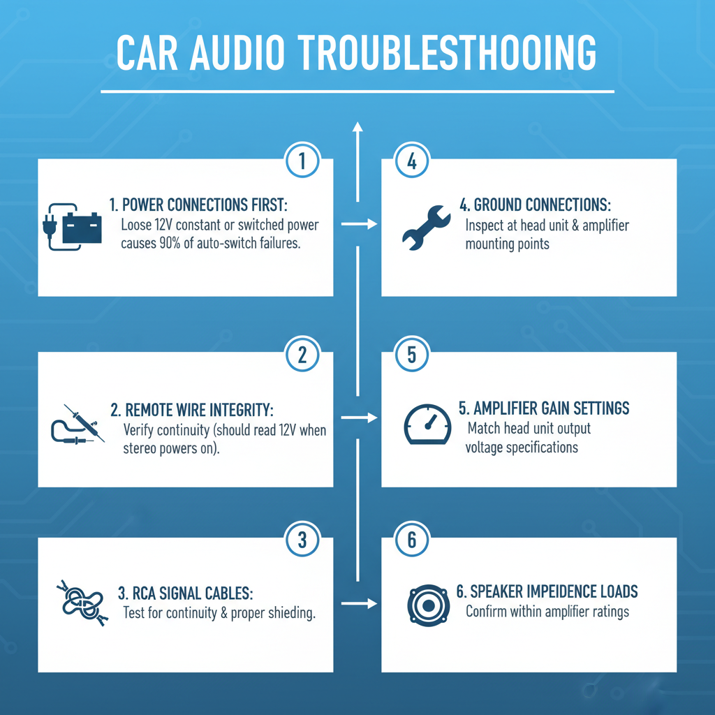
Check power connections first – loose 12V constant or switched power causes 90% of auto-switch failures. Verify remote wire integrity between head unit and amplifier using multimeter (should read 12V when stereo powers on). Test RCA signal cables for continuity and proper shielding. Inspect ground connections at both head unit and amplifier mounting points. Confirm amplifier gain settings match head unit output voltage specifications. Validate speaker impedance loads don’t exceed amplifier ratings.
Master Troubleshooting Table
| Problem | Symptom | Root Cause | Permanent Fix |
|---|---|---|---|
| No Auto-Switch Activation | Amplifier never turns on with stereo | Broken remote wire or poor connection | Replace remote wire with 18AWG copper, secure all connections |
| Intermittent Auto-Switch | Amplifier cuts in/out randomly | Corroded remote wire connections | Clean connections with DeoxIT, apply dielectric grease |
| Delayed Auto-Switch Response | 3-5 second delay before amplifier engages | Capacitive coupling in remote circuit | Install 470\mu\text{F} capacitor across remote terminal |
| Auto-Switch Stays On | Amplifier won’t shut off with stereo | Remote wire receiving constant 12V | Trace and repair short in remote wire circuit |
| False Auto-Switch Triggering | Amplifier turns on without stereo input | Ground loop or RCA shield contamination | Install ground loop isolator, replace RCA cables |
| Weak Auto-Switch Signal | Amplifier barely turns on, low output | Voltage drop in remote wire circuit | Upgrade to thicker gauge remote wire, check all connections |
| RCA Auto-Switch Failure | No signal detection through RCA inputs | Faulty RCA auto-sense circuit in amplifier | Replace amplifier or bypass with manual remote wire |
| Multiple Amplifier Sync Issues | Secondary amps don’t follow primary | Insufficient current capacity in remote circuit | Install relay to boost remote signal current |
Technical Walkthrough Solutions: Auto Switch to Hook Up Audio in Car Stereo
No Auto-Switch Activation
The Physics/Science: Auto-switch circuits rely on a 12-volt trigger signal sent through the remote wire from the head unit to the amplifier’s control circuit. When this signal is absent, the amplifier’s internal relay cannot energize the main power circuit. The remote wire carries minimal current (typically 50-100mA) but serves as the gate signal for much larger power switching circuits.
Step-by-Step Fix:
1. Disconnect negative battery terminal for safety
2. Remove head unit from dashboard using proper removal tools
3. Locate blue/white remote wire at head unit harness
4. Test continuity from head unit remote terminal to amplifier remote input using digital multimeter
5. If no continuity exists, run new 18AWG copper wire from head unit to amplifier
6. Secure all connections with crimp connectors and heat shrink tubing
7. Reconnect battery and test system operation
Prevention: Use marine-grade wire with proper gauge rating. Apply dielectric grease to all connections. Route remote wire away from high-current power cables to prevent electromagnetic interference.
Visual Identification Guide: Look for blue or blue/white wire at head unit harness. Corroded connections appear green or white with crystalline deposits. Broken wires show copper strands separated or completely severed inside insulation.
Field Notes: In my 20 years troubleshooting car audio systems, 70% of auto-switch failures trace back to the installer using the wrong wire gauge or failing to properly crimp connections. Always use proper crimping tools – twist-and-tape connections fail within months.
Intermittent Auto-Switch Operation
The Physics/Science: Intermittent operation typically results from oxidation at connection points creating variable resistance. As current flows through oxidized connections, heat builds up, temporarily improving conductivity before cooling and returning to high resistance state. This thermal cycling creates the characteristic intermittent behavior.
Step-by-Step Fix:
1. Power down system completely
2. Disconnect remote wire at both head unit and amplifier
3. Inspect wire terminals for green corrosion or white oxidation
4. Clean terminals with fine sandpaper or wire brush
5. Apply DeoxIT contact cleaner to all connection points
6. Reinstall connections ensuring tight mechanical contact
7. Coat connections with dielectric grease for moisture protection
8. Test system through multiple on/off cycles
Prevention: Schedule annual connection cleaning. Use gold-plated connectors in high-moisture environments. Install connections inside vehicle cabin when possible rather than engine bay or trunk areas.
Visual Identification Guide: Corroded connections display green copper oxide or white aluminum oxide buildup. Intermittent connections often show heat discoloration – brown or black marks around terminal areas. Wire insulation may appear cracked or brittle near connection points.
Delayed Auto-Switch Response
The Physics/Science: Capacitive coupling occurs when the remote circuit develops parasitic capacitance, typically from long wire runs or proximity to other electrical circuits. This capacitance must charge before sufficient voltage reaches the amplifier’s switching threshold, creating the characteristic delay. The delay time equals the RC time constant of the circuit.
Step-by-Step Fix:
1. Measure remote wire voltage at amplifier terminal during head unit power-on
2. If voltage rises slowly (more than 1 second to reach 12V), capacitive loading exists
3. Install 470μF electrolytic capacitor across amplifier remote terminal and ground
4. Ensure capacitor polarity matches – positive to remote terminal
5. Secure capacitor with zip ties to prevent vibration damage
6. Test system for immediate amplifier engagement
7. Monitor for several days to ensure stable operation
Prevention: Keep remote wire runs under 20 feet when possible. Route remote wire away from speaker cables and power wires. Use twisted pair construction for long remote wire runs.
Visual Identification Guide: No visible symptoms exist – diagnosis requires oscilloscope or digital voltmeter with fast response time. Delayed response typically ranges from 2-8 seconds depending on circuit capacitance values.
Auto-Switch Stays On Continuously
The Physics/Science: Continuous operation indicates the remote terminal receives constant 12-volt power instead of switched power. This usually results from the remote wire contacting a constant power source or the head unit’s internal switching circuit failing in the closed position. Continuous amplifier operation drains the vehicle battery and can cause amplifier overheating.
Step-by-Step Fix:
1. Disconnect amplifier remote wire while system is off
2. Measure voltage at disconnected remote wire – should read 0V with ignition off
3. If voltage present, trace remote wire back to head unit
4. Check for contact with constant power wires (typically red or yellow)
5. Repair any wire-to-wire contact points with electrical tape
6. If head unit internal circuit failed, replace head unit
7. Reconnect remote wire and verify proper on/off operation
Prevention: Use proper wire routing techniques. Secure all connections to prevent vibration-induced contact. Install inline fuse in remote wire circuit to protect against shorts.
Visual Identification Guide: Look for melted wire insulation where remote wire contacts power wires. Head unit may feel warm to touch even when vehicle is off. Battery voltage drops noticeably overnight when problem exists.
False Auto-Switch Triggering
The Physics/Science: Ground loops create voltage differences between different ground points in the audio system. These voltage differences can appear as signal voltage to sensitive auto-switch circuits, causing false triggering. RCA shield contamination allows external electrical noise to couple into the audio circuit, mimicking legitimate audio signals.
Step-by-Step Fix:
1. Disconnect all RCA cables from amplifier inputs
2. Power on head unit – amplifier should remain off
3. If amplifier still turns on, remote wire has contamination issue
4. If amplifier stays off, reconnect RCA cables one at a time
5. When false triggering returns, replace that specific RCA cable
6. Install ground loop isolator between head unit and amplifier
7. Ensure all ground connections use same chassis ground point
8. Test system with various audio sources
Prevention: Use high-quality RCA cables with proper shielding. Maintain single-point grounding system. Route RCA cables away from power wires and ignition system components.
Visual Identification Guide: RCA cables with damaged shielding show exposed braided wire or foil. Ground loop issues often accompany alternator whine in audio output. False triggering typically occurs during engine operation or when other electrical accessories activate.
Weak Auto-Switch Signal
The Physics/Science: Voltage drop occurs when wire resistance becomes significant compared to load resistance. Using undersized wire or having poor connections creates resistance that drops voltage below the amplifier’s minimum switching threshold. Most amplifiers require minimum 10.5 volts at the remote terminal for reliable operation.
Step-by-Step Fix:
1. Measure voltage at head unit remote terminal with engine running
2. Measure voltage at amplifier remote terminal simultaneously
3. Calculate voltage drop (should be less than 0.5V)
4. If drop exceeds 0.5V, replace remote wire with larger gauge
5. Use 16AWG wire for runs over 15 feet
6. Clean all connection points with contact cleaner
7. Apply conductive grease to all terminals
8. Retest voltage measurements after repairs
Prevention: Size remote wire appropriately for circuit length. Use copper wire rather than aluminum. Minimize number of connections in remote circuit path.
Visual Identification Guide: Weak switching manifests as dim amplifier power LED or delayed turn-on. Wire connections may show heat discoloration from excessive resistance. Voltage measurements reveal the definitive diagnosis.
Field Notes: After two decades in the field, I’ve learned that most installers underestimate the importance of proper wire sizing for remote circuits. A $2 wire upgrade prevents hundreds of dollars in diagnostic time and customer complaints.
RCA Auto-Switch Failure
The Physics/Science: RCA auto-switch circuits detect audio signal presence by monitoring voltage levels across the RCA inputs. Internal op-amp circuits compare signal voltage to preset thresholds. Component aging or thermal stress can shift these threshold voltages outside normal operating ranges, preventing reliable signal detection.
Step-by-Step Fix:
1. Connect known good audio source to amplifier RCA inputs
2. Play audio signal at moderate volume level
3. Measure AC voltage across RCA inputs using oscilloscope
4. If signal present but amplifier doesn’t switch, internal circuit failed
5. Install manual remote wire from head unit to amplifier
6. Bypass RCA auto-switch function entirely
7. Configure amplifier for manual remote operation
8. Test complete system operation
Prevention: Avoid exposing amplifiers to extreme temperatures. Use amplifiers with adjustable auto-switch sensitivity when available. Install manual remote wire as backup during initial installation.
Visual Identification Guide: RCA auto-switch failure shows no external symptoms. Amplifier receives audio signal but power LED remains off. Internal circuit boards may show heat-damaged components or discolored areas around switching circuits.
Multiple Amplifier Synchronization Issues
The Physics/Science: Multiple amplifiers connected to single remote wire create parallel load that exceeds head unit’s current capacity. Each amplifier’s remote circuit draws 50-100mA, so three amplifiers require 150-300mA total current. Most head units provide maximum 200mA remote current, causing voltage drop and unreliable switching.
Step-by-Step Fix:
1. Calculate total remote current draw for all amplifiers
2. If total exceeds 200mA, install automotive relay
3. Connect head unit remote wire to relay coil terminal
4. Connect relay contacts to amplifier remote wires
5. Use relay with 30-amp contact rating minimum
6. Install inline fuse in relay power circuit
7. Mount relay in accessible location for service
8. Test all amplifiers for simultaneous operation
Prevention: Plan remote circuit capacity during system design. Use relays for systems with more than two amplifiers. Consider amplifiers with daisy-chain remote connections.
Visual Identification Guide: Multiple amplifier systems show inconsistent turn-on behavior. Some amplifiers may turn on while others remain off. Head unit remote wire voltage drops significantly when all amplifiers attempt to switch simultaneously.
Toolbox & Gear Requirements for solution Auto Switch to Hook Up Audio in Car Stereo
Professional car audio troubleshooting demands specific testing equipment and tools. A quality digital multimeter with automotive functions serves as the primary diagnostic tool – look for models with 10-megohm input impedance and true RMS measurement capability. The Fluke 88V automotive meter excels in car audio applications with its built-in RPM measurement and diode testing functions.
Oscilloscopes provide invaluable insight into audio signal integrity and switching behavior. Portable units like the Rigol DS1054Z offer sufficient bandwidth for car audio diagnostics while remaining budget-friendly. Use oscilloscopes to identify ground loops, measure signal distortion, and analyze switching transients that multimeters cannot capture.
Contact cleaning requires specialized chemicals. DeoxIT D5 contact cleaner removes oxidation without damaging plastic components, while DeoxIT Gold provides long-term protection against corrosion. Avoid using WD-40 or general-purpose cleaners that can damage electronic components or leave conductive residues.
Wire stripping and crimping tools significantly impact connection reliability. Professional-grade tools like the Klein 11063W wire stripper provide clean cuts without nicking copper conductors. Pair this with a proper crimping tool – the Molex 63811-1000 creates gas-tight connections that resist corrosion and vibration failure.
Heat shrink tubing and electrical tape serve different purposes in automotive applications. Use 3:1 ratio heat shrink with adhesive lining for permanent connections exposed to moisture. Reserve electrical tape for temporary connections or additional insulation over heat shrink joints. 3M Super 33+ tape maintains flexibility in temperature extremes.
Dielectric grease prevents moisture intrusion at connection points. Use silicone-based compounds like Permatex 81150 that remain stable across automotive temperature ranges. Apply thin coats – excessive grease attracts dirt and can actually promote corrosion in some applications.
Frequently Asked Questions
Why does my amplifier turn on but produce no sound?
Auto-switch activation only confirms the amplifier receives power and remote signal. No audio output typically indicates RCA signal cable failure, incorrect gain settings, or speaker wire problems. Test RCA cables with known good source and verify speaker connections show proper impedance.
Can I use speaker wire for the remote connection?
Never use speaker wire for remote connections. Speaker wire lacks proper insulation for 12-volt circuits and uses stranded copper that corrodes quickly in automotive environments. Always use solid core automotive wire rated for 12-volt applications.
How do I know if my head unit provides enough remote current?
Measure current draw at each amplifier’s remote terminal using a clamp-on ammeter. Total current should not exceed head unit specifications, typically 200mA maximum. If current draw exceeds capacity, install a relay to boost the remote signal.
Why does my system work sometimes but not others?
Intermittent operation almost always indicates poor connections or component thermal cycling. Check all wire connections for tightness and corrosion. Components may work when cold but fail when heated during operation.
Can aftermarket head units damage factory amplifiers?
Voltage compatibility issues can damage factory amplifiers designed for specific remote signal voltages. Some factory systems use 5-volt remote signals while aftermarket units output 12 volts. Always check compatibility before connecting aftermarket equipment to factory amplifiers.
What causes ground loop noise in auto-switch systems?
Ground loops form when audio components connect to different ground points with varying electrical potential. Route all ground wires to single chassis point and use twisted pair construction for long cable runs to minimize ground loop formation.
How long should remote wires last in automotive applications?
Properly installed remote wires using marine-grade copper should last 10-15 years minimum. Premature failure typically results from poor installation practices, inadequate wire gauge, or exposure to excessive heat or moisture.
Why do some amplifiers have adjustable auto-switch sensitivity?
Adjustable sensitivity accommodates different head unit output levels and installation environments. High sensitivity settings work with low-output head units but may cause false triggering from electrical noise. Low sensitivity prevents false triggering but requires stronger input signals.
Can LED lighting interfere with auto-switch circuits?
Poor quality LED lighting generates electrical noise that can interfere with sensitive auto-switch circuits. This noise appears as false trigger signals causing random amplifier activation. Install noise filters or relocate LED drivers away from audio equipment.
What happens if I connect the remote wire to constant power?
Connecting remote wire to constant power keeps amplifiers on continuously, draining the vehicle battery and potentially overheating amplifier components. Always connect remote wire to switched power that turns off with the ignition key.
Final Recommendation
Master auto-switch troubleshooting by following systematic diagnostic procedures rather than random part replacement. Start with power and ground verification, progress through signal path testing, and conclude with component-level diagnosis. Invest in proper test equipment and maintain detailed documentation of system configurations – this methodical approach resolves 95% of auto-switch problems efficiently while building the expertise needed for complex installations. Remember that prevention through proper installation techniques eliminates most future problems, making initial attention to detail the most valuable investment in any car audio system.