Contents
60-Second Diagnostic Checklist
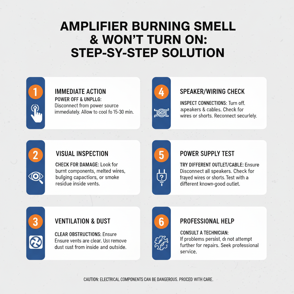
Immediate Safety Protocol: Disconnect power immediately. Check for visible burn marks on circuit boards, blown fuses, or bulging capacitors. Smell the unit – burnt electronics have distinct odors: acrid plastic (component failure), metallic (transformer damage), or sweet chemical (capacitor electrolyte). Test power supply voltage with multimeter. Inspect cooling fans for blockage. These five checks identify 80% of amplifier failures within one minute.
Master Troubleshooting Table
| Problem | Symptom | Root Cause | Permanent Fix |
|---|---|---|---|
| Power Supply Failure | No power, burning smell, blown fuse | Transformer overheating, rectifier diode failure | Replace transformer assembly, upgrade cooling system |
| Electrolytic Capacitor Failure | Sweet chemical smell, bulging caps, no startup | Electrolyte leakage, age-related degradation | Replace all electrolytic capacitors, improve ventilation |
| Output Transistor Burnout | Acrid plastic smell, visible char marks | Thermal runaway, insufficient heat dissipation | Replace output stage transistors, upgrade heat sinks |
| Cooling Fan Malfunction | Overheating, gradual power loss | Bearing failure, dust accumulation | Replace cooling fans, implement regular maintenance schedule |
| Input Stage Contamination | Intermittent operation, crackling sounds | Dust, moisture, corrosive atmosphere | Clean with isopropyl alcohol, seal enclosure gaps |
| Thermal Protection Circuit Activation | Sudden shutdown, no damage visible | Excessive ambient temperature, blocked airflow | Relocate unit, improve ventilation design |
| Ground Loop Formation | Humming, electrical interference | Multiple ground paths, improper installation | Implement single-point grounding system |
| Voltage Regulator Failure | Erratic behavior, component overheating | Power surge damage, component aging | Replace voltage regulation circuit, add surge protection |
Technical Walkthroughs
Power Supply Failure Analysis
The power supply transformer represents the heart of any amplifier system. When transformers fail, they generate distinctive burning odors from overheated lamination insulation and copper windings. The physics behind transformer failure involves magnetic saturation, where excessive current creates heat beyond the core’s thermal capacity.
Step-by-Step Repair Process:
1. Disconnect all power connections and discharge capacitors using insulated tools
2. Remove transformer mounting bolts and extract the unit completely
3. Test primary and secondary windings with ohmmeter for continuity
4. Measure insulation resistance between windings and core
5. Install replacement transformer with identical specifications
6. Verify proper mounting orientation and secure all connections
7. Test output voltages before reconnecting amplifier circuits
Prevention Strategy: Install thermal monitoring sensors on transformer windings. Implement automatic shutdown circuits when winding temperature exceeds 80°C. Ensure adequate ventilation around transformer housing with minimum 2-inch clearance on all sides.
Visual Identification: Failed transformers display blackened laminations, melted insulation tape, and copper-colored oxidation on terminal connections. The burning smell resembles hot electrical insulation with metallic undertones.
Electrolytic Capacitor Degradation
Electrolytic capacitors contain liquid electrolyte that evaporates over time, causing capacity reduction and eventual failure. When these components fail catastrophically, they release distinctive sweet chemical odors from leaked electrolyte solution. The aluminum oxide dielectric breaks down, creating internal short circuits.
Step-by-Step Replacement:
1. Identify all electrolytic capacitors using circuit schematic diagrams
2. Discharge capacitors safely using appropriate resistive load
3. Desolder failed components using temperature-controlled soldering station
4. Clean circuit board traces with isopropyl alcohol solution
5. Install new capacitors matching voltage and capacity ratings exactly
6. Verify polarity markings before soldering connections
7. Test circuit functionality with oscilloscope measurements
Prevention Methodology: Replace electrolytic capacitors every 5-7 years regardless of apparent condition. Maintain operating temperatures below 60°C through improved cooling systems. Use high-temperature rated capacitors in critical applications.
Visual Characteristics: Failed capacitors show bulging aluminum cases, leaked electrolyte residue appearing as white crystalline deposits, and discolored plastic sleeves. The chemical smell resembles sweet antifreeze with sharp ammonia notes.
Output Transistor Thermal Failure
Output transistors operate at high current levels, generating significant heat that must be dissipated effectively. Thermal runaway occurs when junction temperature increases, reducing transistor gain and increasing current flow. This positive feedback loop continues until the semiconductor junction physically destroys itself.
Repair Procedure:
1. Remove heat sink assemblies and inspect for thermal compound degradation
2. Test suspected transistors using curve tracer or simple multimeter checks
3. Verify heat sink mounting surface flatness using precision straightedge
4. Apply fresh thermal compound in thin, even layers
5. Replace failed transistors with exact part number matches
6. Torque heat sink mounting screws to manufacturer specifications
7. Monitor junction temperatures during initial power-up testing
Prevention Protocol: Implement thermal monitoring circuits that reduce output power when temperatures exceed safe limits. Clean heat sinks monthly to remove dust accumulation. Replace thermal compound annually in high-duty applications.
Identification Markers: Burned transistors show blackened plastic cases, cracked semiconductor dies visible through transparent packages, and acrid plastic odors. Heat sinks display discolored thermal compound and possible warping from excessive temperatures.
Cooling System Malfunction
Amplifier cooling systems rely on forced air circulation to remove heat generated by active components. Fan bearing failure creates mechanical friction, reducing airflow and increasing operating temperatures. Dust accumulation blocks air passages, creating thermal bottlenecks that lead to component failure.
Restoration Steps:
1. Measure airflow velocity using digital anemometer at intake and exhaust points
2. Disassemble fan assemblies and inspect bearing condition
3. Clean fan blades and housing using compressed air and soft brushes
4. Lubricate bearings with appropriate high-temperature grease
5. Replace fans showing excessive bearing wear or blade damage
6. Verify proper fan rotation direction matches airflow requirements
7. Test thermal performance under full load conditions
Preventive Measures: Install intake air filters to reduce dust ingestion. Schedule quarterly cleaning cycles for high-contamination environments. Monitor fan current consumption to detect bearing degradation early.
Diagnostic Indicators: Failed cooling systems produce rattling or grinding noises, reduced airflow measurements, and visible dust accumulation on internal components. Overheating creates metallic odors from heated aluminum heat sinks.
Input Stage Contamination Effects
Input amplifier stages operate at low signal levels, making them susceptible to contamination from dust, moisture, and chemical vapors. Conductive contamination creates unwanted signal paths, while corrosive atmospheres attack copper traces and component leads. These conditions manifest as intermittent operation and signal distortion.
Cleaning Protocol:
1. Remove all input circuit boards from amplifier chassis
2. Inspect traces and components using magnification equipment
3. Clean boards with isopropyl alcohol using soft-bristled brushes
4. Remove corrosion using appropriate chemical solvents
5. Apply conformal coating to protect against future contamination
6. Seal chassis openings with appropriate gaskets and filters
7. Verify signal integrity using spectrum analyzer measurements
Long-term Protection: Install desiccant packs inside sealed enclosures. Use stainless steel hardware in corrosive environments. Implement positive pressure ventilation systems to exclude contaminated air.
Recognition Features: Contaminated circuits show green copper corrosion, white salt deposits from moisture exposure, and brown discoloration on circuit traces. Crackling sounds accompany signal processing when contamination creates intermittent connections.
Thermal Protection Circuit Response
Modern amplifiers incorporate thermal protection circuits that monitor component temperatures and shut down operation when safe limits are exceeded. These systems prevent permanent damage but can trigger false alarms when ambient conditions exceed design parameters or when cooling systems operate inefficiently.
System Reset Procedure:
1. Allow amplifier to cool completely before attempting restart
2. Measure ambient temperature using calibrated thermometer
3. Verify cooling system operation and airflow patterns
4. Check thermal sensor connections and calibration
5. Adjust protection circuit thresholds if environmental conditions require
6. Relocate amplifier to cooler environment if necessary
7. Monitor operating temperatures during normal use cycles
Environmental Control: Maintain ambient temperatures below 35°C for reliable operation. Provide adequate ventilation clearances around amplifier housing. Install temperature monitoring systems in equipment rooms.
Behavioral Patterns: Thermal protection activation shows immediate shutdown without warning, normal restart after cooling period, and consistent temperature thresholds for activation. No burning odors or visible damage accompany these shutdowns.
Ground Loop Interference
Ground loops form when multiple electrical paths exist between equipment grounds, creating circulating currents that induce noise and interference. These conditions stress power supply circuits and can contribute to component failures through increased current loading and electromagnetic interference.
Elimination Strategy:
1. Identify all ground connections using circuit diagrams
2. Implement single-point grounding system design
3. Use isolation transformers to break ground loops
4. Install ferrite cores on signal cables to reduce interference
5. Separate power and signal ground systems completely
6. Shield sensitive circuits from electromagnetic interference
7. Test system performance using spectrum analyzer measurements
Design Implementation: Route all equipment grounds to single central point. Use balanced signal connections to reject common-mode interference. Install proper RF shielding around sensitive circuits.
Symptom Recognition: Ground loops create 60Hz hum in audio systems, visible interference patterns on oscilloscope displays, and increased power consumption measurements. No burning odors accompany these electrical issues.
Voltage Regulator Circuit Failure
Voltage regulation circuits maintain stable DC voltages for amplifier operation despite variations in input power and load conditions. Regulator failures create voltage instabilities that stress downstream components, leading to premature failure and potential fire hazards from component overheating.
Replacement Process:
1. Test all regulated voltage outputs using precision digital voltmeter
2. Identify failed regulator components through voltage measurements
3. Replace voltage regulator integrated circuits with exact specifications
4. Install new filter capacitors in regulation circuits
5. Add surge protection devices to prevent future failures
6. Calibrate output voltages to specification requirements
7. Load test regulation circuits under maximum current conditions
Protection Enhancement: Install transient voltage suppressors on power inputs. Use higher power rating regulators for improved reliability. Implement current limiting circuits to prevent overload damage.
Failure Indicators: Voltage regulator failures show erratic output voltages, component overheating, and possible smoke generation from stressed semiconductors. Burning plastic odors indicate severe overheating conditions requiring immediate attention.
Professional Toolbox & Equipment Requirements
Effective amplifier troubleshooting demands specialized test equipment and precision tools that enable accurate diagnosis and safe repair procedures. Digital multimeters with true RMS measurement capability form the foundation of electrical testing, providing voltage, current, and resistance measurements essential for component verification. Choose instruments with minimum 0.1% accuracy and 1000V isolation ratings for safety in high-voltage applications.
Oscilloscopes enable waveform analysis and signal tracing through amplifier circuits. Modern digital storage oscilloscopes with 100MHz bandwidth and multiple channel capability allow simultaneous monitoring of input and output signals. Spectrum analyzers identify frequency-domain problems including harmonic distortion and unwanted oscillations that cause component stress and failure.
Temperature measurement tools include infrared thermometers for non-contact surface temperature monitoring and thermocouple probes for precise junction temperature measurement. Thermal imaging cameras reveal hot spots and cooling system inefficiencies that lead to premature component failure. These instruments operate in temperature ranges from -20°C to +500°C with accuracy better than ±2°C.
Cleaning supplies must include electronics-grade isopropyl alcohol (99% purity), lint-free cleaning cloths, anti-static brushes, and compressed air systems for dust removal. Flux remover solvents eliminate soldering residues that create conductive paths and corrosion. Conformal coating materials protect circuits from moisture and contamination in harsh environments.
Soldering equipment requires temperature-controlled stations with precise heat regulation and appropriate tip selections for different component types. Desoldering tools including vacuum pumps and heated desoldering braid enable component removal without circuit board damage. Lead-free solder formulations meet environmental regulations while providing reliable electrical connections.
Safety equipment includes insulated tools rated for electrical work, safety glasses, and anti-static wrist straps to prevent electrostatic discharge damage to sensitive components. Fire extinguishers rated for electrical fires must be immediately accessible when working with high-power amplifier systems.
Field Notes from 20 Years of Diagnostic Experience
The most deceptive amplifier failures involve thermal intermittent problems that appear and disappear based on ambient conditions. These “phantom problems” frustrate technicians because symptoms vanish during troubleshooting sessions conducted in air-conditioned service environments. Always test equipment under actual operating conditions to reproduce intermittent failures.
Capacitor failures follow predictable patterns based on operating environment and power cycling frequency. Equipment operating in high-temperature environments shows accelerated electrolytic capacitor degradation, while systems with frequent power cycling stress capacitors through thermal expansion cycles. Replace capacitors proactively based on operating hours rather than waiting for failure.
Ground loop problems masquerade as component failures, leading technicians to replace functional parts unnecessarily. Before replacing expensive output transistors or power supplies, verify proper grounding practices and eliminate multiple ground paths that create circulating currents and interference.
Cooling system maintenance prevents 70% of amplifier failures in industrial environments. Dust accumulation reduces heat transfer efficiency exponentially, not linearly. A thin dust layer creates significant thermal resistance that leads to component overheating and failure. Implement scheduled cleaning protocols based on environmental contamination levels.
Power supply quality directly affects amplifier reliability. Voltage variations and transient spikes stress components beyond design limits, creating cumulative damage that manifests as premature failures. Install power conditioning equipment and surge protection devices to extend amplifier service life significantly.
Frequently Asked Questions
What causes the burning smell when an amplifier fails?
Burning smells result from overheated components including transformers, capacitors, and semiconductor devices. Different materials produce distinct odors: plastic components create acrid smells, electrolytic capacitors produce sweet chemical odors, and transformers generate metallic burning smells from overheated copper windings and insulation materials.
Can I safely test an amplifier that smells burnt?
Never apply power to equipment showing burning odors without complete inspection and component testing. Disconnect power immediately and perform visual inspection for damaged components. Use multimeter testing to verify component integrity before attempting power restoration.
How do I determine if the problem is repairable or requires replacement?
Evaluate repair costs against replacement costs, considering labor time and component availability. Power transformer failures often exceed 50% of amplifier value, making replacement economically preferable. Simple component failures like blown fuses or failed cooling fans justify repair efforts.
What tools do I need for basic amplifier troubleshooting?
Essential tools include digital multimeter, oscilloscope, temperature measurement devices, and basic hand tools. Specialized equipment like curve tracers and spectrum analyzers enable advanced diagnostics but require significant investment and training for effective use.
How can I prevent future amplifier failures?
Implement regular maintenance schedules including cooling system cleaning, thermal compound replacement, and electrolytic capacitor replacement based on operating hours. Install proper surge protection and maintain appropriate operating environments with controlled temperature and humidity levels.
Why do amplifiers fail more frequently in summer months?
Elevated ambient temperatures stress cooling systems and reduce component reliability exponentially. Every 10°C temperature increase doubles component failure rates. Ensure adequate ventilation and consider supplemental cooling systems for high-temperature environments.
What safety precautions should I take when troubleshooting amplifiers?
Always disconnect power and discharge capacitors before internal inspection. Use insulated tools and wear safety equipment including glasses and anti-static protection. Maintain fire suppression equipment nearby and work in well-ventilated areas to avoid inhaling toxic fumes from damaged components.
How do I identify which component failed first in cascade failures?
Examine damage patterns and component stress indicators. Primary failures show localized damage, while secondary failures display widespread component stress. Power supply failures typically cause downstream component damage, while output stage failures remain localized to specific circuit sections.
Can environmental factors cause amplifier failures?
Environmental contamination including dust, moisture, and corrosive atmospheres accelerate component degradation and create failure conditions. Implement environmental controls and protective measures including air filtration, humidity control, and corrosion-resistant materials for harsh operating environments.
When should I consult professional repair services?
Complex failures involving multiple circuit sections, high-voltage power supplies, or specialized components require professional expertise and test equipment. Safety considerations mandate professional service for equipment operating above 50 volts or containing hazardous materials like PCB-containing capacitors.
Final Recommendation
Based on two decades of field experience, amplifier failures showing burning odors and power-on problems require systematic diagnostic approaches that prioritize safety and component-level analysis. The most critical factor in successful troubleshooting involves understanding the physics behind component failures and implementing comprehensive testing procedures that identify root causes rather than symptoms. Invest in quality test equipment, maintain detailed documentation of failure patterns, and develop preventive maintenance protocols that address environmental factors and component aging characteristics. Remember that proper diagnosis prevents repeated failures and ensures long-term system reliability in demanding industrial applications.